Interfacing & Displaysintermediatedesign notes
Level Shifting Done Right: Dividers, MOSFETs and Optocouplers
When you need level shifting, why dividers fail at speed, how the 2N7002 bi-directional circuit works, and when to use an optocoupler instead.
By ADIY12 min read
Technical review pending. Figures marked “verify” or “check your part” have not been confirmed against your exact hardware revision. Check the manufacturer datasheet before relying on them in a design.
Connecting a 5 V microcontroller to a 3.3 V module is the most common way engineers destroy parts, and the reason it keeps happening is that it usually works at first. The damage is cumulative, the failure is delayed, and by then nobody suspects the wiring.
1. Do you actually need it?#
Start here, because half the level shifters fitted are unnecessary and some of the ones omitted were essential. The answer depends entirely on direction.
| Direction | Risk | Usually |
|---|---|---|
| 3.3 V output → 5 V input | Signal may not be recognised as high | Often works. Many 5 V inputs accept anything above roughly 2 V as high. |
| 5 V output → 3.3 V input | Damage to the 3.3 V part | Shift it, unless the input is explicitly 5 V tolerant. |
| Bi-directional, such as I2C | Both of the above | Needs a proper bi-directional solution. |
Check the datasheet, in two places#
- Input high threshold (VIH). Will your 3.3 V output be recognised as high by the 5 V receiver? If VIH is specified as a fraction of the supply, a 5 V part might need 3.5 V and 3.3 V will be marginal.
- Absolute maximum input voltage. Is the 3.3 V input 5 V tolerant? Some are, explicitly. Most are not. This line in the datasheet is the whole answer.
2. The resistor divider, and its real limit#
Two resistors, one signal, done. For a 5 V output driving a 3.3 V input, a common arrangement is roughly a 1 kΩ series resistor with a 2 kΩ to ground, giving about 3.3 V from a 5 V input.
The divider is also strictly one direction. It cannot work for I2C, or for any shared bidirectional line.
3. The MOSFET bi-directional circuit#
This is the standard solution, used on the ADIY 2N7002 bi-directional module and on essentially every four-channel level shifter board you will encounter.
One small MOSFET per channel, with a pull-up resistor on each side:
- The MOSFET source connects to the low voltage side, with a pull-up to the low voltage supply
- The MOSFET drain connects to the high voltage side, with a pull-up to the high voltage supply
- The MOSFET gate is tied to the low voltage supply
Why this works in both directions#
| State | What happens |
|---|---|
| Both sides idle | Both pull-ups hold their side high. Gate and source are both at the low supply, so VGS is zero, the MOSFET is off, and the two sides sit independently at their own high levels. |
| Low side pulled down | Source goes to ground while the gate stays at the low supply, so VGS becomes positive, the MOSFET turns on, and it pulls the high side down too. |
| High side pulled down | Current flows through the MOSFET's intrinsic body diode, pulling the source down. That creates a positive VGS, so the device then turns on properly and completes the pull-down. |
4. Optocouplers, for isolation not translation#
An optocoupler passes the signal as light between an LED and a photodetector, with no electrical connection at all. The ADIY PC817 module is a two-channel example.
When you actually need isolation#
- Different ground references. Long cable runs between equipment, where the two grounds sit at genuinely different potentials, and connecting them would push current down your signal ground.
- Mains-adjacent circuits. Keeping a low-voltage control side galvanically separated from anything near mains. See our relay module article, which covers the same idea and the JD-VCC jumper that quietly defeats it.
- Noisy loads. Motor drives and switching equipment that would otherwise couple noise back into your controller.
- Protecting expensive hardware from a cheaper, more exposed circuit.
What it costs you#
- Speed. Optocouplers are considerably slower than MOSFET shifters. Fine for a UART, unsuitable for fast SPI.
- Current. The LED needs real drive current, typically several milliamps per channel.
- Inversion. The common configuration inverts the signal. Account for it in firmware or hardware.
- A second supply. Isolation is only isolation if the two sides have separate supplies. Powering both from one supply defeats the entire purpose, which is exactly the JD-VCC mistake.
5. Dedicated translator ICs#
For high speed, many channels, or a production design, purpose-built level translator ICs are the right answer. They handle push-pull signals at speeds the MOSFET circuit cannot, come in fixed-direction and auto-direction variants, and integrate many channels in one package.
The trade is that they are less forgiving. Direction control pins must be driven correctly, supply sequencing may matter, and auto-direction parts have their own rules about what they can and cannot sense. Read the datasheet properly rather than assuming a drop-in.
6. Decision table#
| Situation | Use | Why |
|---|---|---|
| 3.3 V out → 5 V in, slow | Often nothing | Check VIH. Frequently already valid. |
| 5 V out → 3.3 V in, slow, one line | Resistor divider | Cheap, adequate within its bandwidth. |
| I2C between 5 V and 3.3 V | MOSFET bi-directional module | Open-drain behaviour matches I2C exactly. |
| SPI at several MHz | Dedicated translator IC | Divider and MOSFET circuits run out of bandwidth. |
| UART, moderate speed, several lines | MOSFET module | Convenient, bi-directional, adequate speed. |
| Different ground potentials | Optocoupler | Only isolation solves this. |
| Mains-adjacent control | Optocoupler, separate supplies | Isolation is a safety property here. |
| Many channels, production design | Translator IC | Fewer parts, better characterised, smaller. |
| Cellular module UART to 5 V MCU | Check the board first | Many breakouts already include it. Measure before adding. |
| ESP32 shield on a 5 V design | Depends per signal | Audit each line for direction and speed separately. |
7. Common mistakes#
| Mistake | Consequence |
|---|---|
| Assuming it works because it works today | Overstress damage is cumulative and often delayed by weeks. |
| Divider on a fast SPI bus | Rounded edges, corrupted data, intermittent faults that look like software bugs. |
| Divider on I2C | Does not work. I2C is bi-directional; a divider is not. |
| MOSFET shifter with gate on the high side | Circuit does not function. The gate must go to the low voltage supply. |
| Optocoupler with a shared supply | No isolation at all. Same error as leaving the JD-VCC jumper in. |
| Forgetting pull-ups on the MOSFET circuit | Lines float. Nothing works. |
| Pull-ups too large for the bus speed | Slow rise times, marginal timing, works on the bench and fails in the product. |
| Shifting a line that is already 5 V tolerant | Harmless but wasteful; adds parts and delay for nothing. |
| Not shifting the supply-sequencing-critical lines | If the 5 V rail comes up before the 3.3 V rail, a 5 V signal can appear at an unpowered 3.3 V input. Consider power sequencing too. |
FAQ#
Do I always need a level shifter between 5V and 3.3V devices?
No, direction matters. A 3.3 V output driving a 5 V input often works, because many 5 V families treat anything above roughly 2 V as high. The dangerous direction is a 5 V output driving a 3.3 V input, which can exceed the absolute maximum rating. Check both the input threshold and whether the input is 5 V tolerant.
Why does a resistor divider fail at higher speeds?
The divider's output resistance combines with the receiving pin's input capacitance to form a low pass filter. At low speeds the signal still settles in time; as frequency rises the edges round off until the receiver never sees a valid level. This is why a divider fine for a slow UART fails on SPI at several megahertz.
How does the 2N7002 bi-directional level shifter work?
A MOSFET sits between the two sides with its gate tied to the lower supply and a pull-up on each side. Pull the low side down and the MOSFET conducts, pulling the high side with it. Pull the high side down and current flows through the body diode, after which the device turns on fully. Both directions work through one component, which is why it is the standard I2C solution.
Can I use an optocoupler as a level shifter?
You can, but that is not its purpose. An optocoupler gives complete galvanic isolation, which a MOSFET shifter does not, and that is its real value. As a pure translator it is slower, needs more drive current and inverts the signal in the common configuration. Use it when you need isolation.
What happens if I connect a 5V output to a 3.3V input?
It may work, work for months then fail, or fail immediately. Many 3.3 V parts have protection diodes to their supply rail, and a 5 V signal forward biases that diode, pushing current into the rail. The failure is often delayed and intermittent, which makes it particularly expensive to diagnose.
Sources#
Sources and further reading#
- NXP application note AN10441, Level shifting techniques in I2C-bus design. The original reference for the bi-directional MOSFET circuit described in section 3.
- 2N7002 MOSFET datasheets, for threshold voltage and body diode behaviour.
- Sharp PC817 optocoupler datasheet, for isolation voltage and switching characteristics.
- Microcontroller datasheets generally, for the input threshold and absolute maximum ratings discussed in section 1.
Products & resources
- ADIY Bi-Directional Logic Level Module Datasheet
- ADIY PC817 2 CH Optocoupler Isolation Module datasheet
Converter Boards
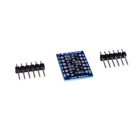
ADIY Bi-Directional Logic Level Module
Because the Arduino (and Basic Stamp) are 5V devices, and most modern sensors, displays, flashcards, and modes are 3.3V-only, many makers find that they need to perform level shifting/conversion to protect the 3.3V…
₹26
Datasheet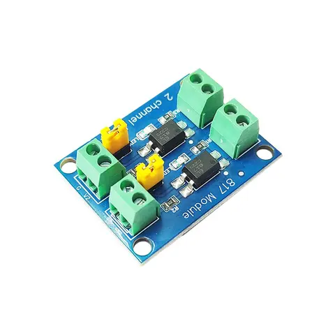
Relay Boards
ADIY PC817 2 Channel Optocoupler Isolation Module
PC817 2 Channel Optocoupler Isolation Module by ADIY is Onboard with 4-Channel PC817 are independent, so they can achieve different voltage control at the same time. Using a 4-way PC817 optocoupler, to achieve the…
₹63
Datasheet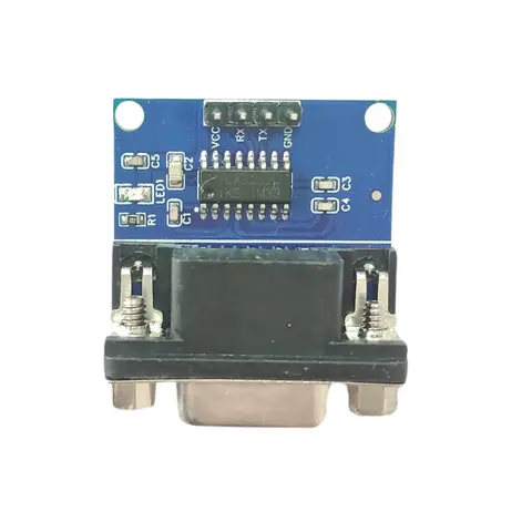
Interface Modules
RS232 to TTL Serial Interface Module
RS232 to TTL Serial Interface Module RS232 to TTL Serial Interface Module by Adiy is a board with the MAX3232 transceiver integrated circuit (IC). It facilitates serial communication between TTL and RS232 ports by…
₹71
Share