
Wireless & Cellularintermediateadiy labs
SIMA7670C AT Commands: 4G LTE Bring-Up to MQTT Publish
Working AT command sequence for the SIMCom A7670C: power budget, baud traps, CSQ and CEREG, APN, HTTP and MQTT publish, with a full Arduino sketch.
By ADIY19 min read
Technical review pending. Figures marked “verify” or “check your part” have not been confirmed against your exact hardware revision. Check the manufacturer datasheet before relying on them in a design.
Most A7670C projects fail in the first ten minutes, and almost never because of the AT commands. This is the bring-up sequence that actually works, the two hardware traps that account for the majority of support tickets, and a complete Arduino sketch that publishes sensor data over 4G.
The SIMCom A7670C is an LTE Cat 1 module. Cat 1 is the sweet spot for a large class of Indian IoT products: enough throughput for telemetry, firmware updates and light image transfer, far cheaper and lower power than Cat 4, and unlike NB-IoT it has broad live network coverage today. If you are building energy meters, asset trackers, vending telemetry, agricultural controllers or remote pump control, this is very likely the module you will end up specifying.
It also has a reputation for being difficult to bring up. That reputation is mostly undeserved. In our experience the failures cluster into two hardware issues that have nothing to do with the AT command set, and once those are dealt with the software side is straightforward. So we will deal with the hardware first.
1. The power supply trap#
This is the single largest cause of A7670C bring-up failures, and it is worth stating bluntly.
The reason is the difference between average and peak current. Supplier documentation for the A7670C quotes idle current in the low single-digit milliamp range, which looks harmless, but also quotes peak current consumption in excess of 2 A. That peak occurs during transmit bursts, and network registration is the first time the module transmits at power.
| Parameter | Value | Status |
|---|---|---|
| Module supply voltage (VBAT) | 3.4 V to 4.2 V | Supplier spec (source stated) |
| Peak current during TX burst | > 2 A | Supplier spec (source stated) |
| Typical idle current, LTE | approx. 3.8 mA | Supplier spec (source stated) |
| Typical idle current, GSM | approx. 3.5 mA | Supplier spec (source stated) |
| Operating temperature | -40 °C to +85 °C | Supplier spec (source stated) |
Note the supply voltage range. The bare module wants 3.4 V to 4.2 V, not 5 V. Breakout boards handle this with an onboard regulator, which is why boards in this family are commonly built around a low-dropout regulator capable of high peak current rather than a generic 3.3 V part. If you are working with a bare module rather than a breakout, the regulator selection is your design problem and it is not a trivial one: it must hold regulation through a 2 A pulse with a fast edge.
What to actually do#
- Use a supply rated 2 A or more. A 5V 2A adapter is the practical minimum for bench work. 3 A gives margin.
- Add bulk capacitance close to the module. A low-ESR electrolytic in the 470 uF to 1000 uF range across the module supply pins, paired with a 100 nF ceramic, absorbs the burst so the rail does not sag. Place it physically close, not at the far end of a breadboard.
- Keep the supply wiring short and thick. Breadboard contact resistance and thin jumper wires are enough to cause a brownout at 2 A. This is a real effect and it catches experienced engineers.
- Share a common ground between the module supply and the microcontroller. Two separate supplies with no ground bond will produce behaviour that looks like random data corruption.
2. The UART baud rate trap#
SIMCom modules in this family typically come up at 115200 baud. That is fine for a hardware UART. It is not fine for SoftwareSerial on a 16 MHz AVR, which cannot receive 115200 reliably. What you observe is garbage characters, partially received responses, or responses that arrive intact for short commands and get mangled for long ones.
You have three options, in descending order of how much we would recommend them:
- Use a board with a spare hardware UART. An Arduino Mega, an ESP32 or an RP2040 board gives you a second real UART and the problem disappears. This is the right answer for anything beyond a quick experiment.
- Lower the module baud rate permanently. Connect to the module once with a USB to TTL adapter at 115200, issue
AT+IPR=9600, thenAT&Wto save it to the profile. The module will now come up at 9600 andSoftwareSerialwill work. - Use the Uno hardware UART and give up the USB serial monitor. Workable but painful to debug, since you lose your window into what is happening.
3. Wiring and logic levels#
| Module pin | Connects to | Notes |
|---|---|---|
| VBAT / VIN | External 2 A supply | Not the Arduino 5V pin. See section 1. |
| GND | Supply GND and Arduino GND | Common ground is mandatory. |
| TXD (module out) | MCU RX | Level shift if required by your board. |
| RXD (module in) | MCU TX | Level shift if required by your board. |
| PWRKEY | MCU GPIO or button | Many boards auto-start. If yours does not, pull PWRKEY low for the duration specified in your board documentation. |
| Antenna | Main LTE antenna | Fit before powering up. See warning below. |
4. Bring-up sequence, command by command#
Work through this sequence in a serial terminal before you write a single line of Arduino code. Every command should be terminated with carriage return. Do not move to the next step until the current one gives the expected response, because each step depends on the previous one succeeding.
AT
  OK
  → Basic UART link is alive. If this fails, your problem is baud rate,
    wiring, level shifting or power. It is not the module firmware.
ATE0
  OK
  → Turn off command echo. Makes parsing responses in code far easier.
AT+CPIN?
  +CPIN: READY
  → SIM detected and unlocked. "SIM not inserted" means seating,
    orientation or a dead SIM holder. "SIM PIN" means the SIM has a PIN set;
    disable it in a phone first, or send AT+CPIN="1234".
AT+CSQ
  +CSQ: 21,99
  → Signal quality. See section 5 for how to read this properly.
AT+CNMP?
  +CNMP: 2
  → Network mode preference. See note below.
AT+COPS?
  +COPS: 0,0,"Operator Name",7
  → Which operator you are camped on, and the access technology.
    The trailing 7 indicates E-UTRAN, meaning you are on LTE.
AT+CEREG?
  +CEREG: 0,1
  → EPS network registration status. This is the one that matters
    for LTE. See section 5.
AT+CGATT?
  +CGATT: 1
  → Attached to the packet domain service. 1 is what you want.
Bring-up sequence. Expected responses shown after each command.
5. Reading CSQ and CEREG properly#
These two responses are where most people misdiagnose. Both are defined in the 3GPP TS 27.007 AT command specification, and the encoding is not intuitive.
AT+CSQ#
The first value is a received signal strength indicator on a scale of 0 to 31, plus the special value 99. It is not a percentage and it is not dBm. To convert to dBm:
RSSI (dBm) = -113 + (2 × CSQ)| CSQ value | RSSI | Practical meaning |
|---|---|---|
| 0 to 9 | -113 to -95 dBm | Marginal. Expect dropped sessions and slow attach. Improve the antenna or relocate. |
| 10 to 14 | -93 to -85 dBm | Usable for low-rate telemetry. Acceptable for a fixed installation. |
| 15 to 19 | -83 to -75 dBm | Good. Comfortable working margin. |
| 20 to 31 | -73 to -51 dBm | Strong. |
| 99 | Unknown | Not a weak signal. No measurement available. Check antenna, SIM and whether the search has completed. |
AT+CEREG?#
The response format is +CEREG: <n>,<stat>. The first number is the unsolicited result code setting, which you configured. The second is the registration status, which is what you care about.
| stat | Meaning | What to do |
|---|---|---|
| 0 | Not registered, not searching | Module is not trying. Check AT+CFUN? is 1, and check network mode preference. |
| 1 | Registered, home network | Proceed. |
| 2 | Not registered, searching | Wait. Attach can take 30 to 60 seconds on first power-up in a new location. |
| 3 | Registration denied | Operator rejected the SIM. Usually an inactive SIM, unpaid account, or an M2M SIM not provisioned for this network. |
| 4 | Unknown | Typically transient. Retry. |
| 5 | Registered, roaming | Fine functionally, but check your tariff. |
Status 3 is the one that wastes the most engineer-hours, because the module and code are both working correctly and the fault is commercial. If you get a persistent 3, put the SIM in a phone and confirm it attaches and passes data before touching anything else.
6. APN and PDP context setup#
Before any IP traffic, you must define a PDP context with your operator APN.
AT+CGDCONT=1,"IP","your.apn.here"
  OK
AT+CGACT=1,1
  OK
  → Activate context 1. May take several seconds.
AT+CGPADDR=1
  +CGPADDR: 1,"10.x.x.x"
  → You have an IP address. You are on the network.
APN values differ by operator and by SIM type. Consumer SIMs and M2M SIMs from the same operator often use different APNs. Get the correct value from your SIM provider rather than from a blog post, including this one. An incorrect APN typically produces a successful registration followed by a failure at context activation, which is a useful diagnostic signature in itself.
7. HTTP GET and POST#
The module has a built-in HTTP stack, so you do not need to implement sockets yourself.
AT+HTTPINIT
  OK
AT+HTTPPARA="URL","http://example.com/api/telemetry"
  OK
AT+HTTPPARA="CONTENT","application/json"
  OK
AT+HTTPDATA=42,10000
  DOWNLOAD
  → Now send exactly 42 bytes of body within 10000 ms.
    {"device":"adiy-01","temp":31.4,"csq":21}
AT+HTTPACTION=1
  OK
  +HTTPACTION: 1,200,17
  → Method 1 is POST. 200 is the HTTP status. 17 is the response length.
AT+HTTPREAD=0,17
  → Read the response body.
AT+HTTPTERM
  OK
For a GET, skip the HTTPDATA step and use AT+HTTPACTION=0.
8. MQTT publish#
For most telemetry applications MQTT is a better fit than HTTP: persistent connection, lower per-message overhead, and built-in quality of service. The A76xx family exposes MQTT through the CMQTT command set.
AT+CMQTTSTART
  +CMQTTSTART: 0
AT+CMQTTACCQ=0,"adiy-device-01"
  OK
  → Client index 0, client ID "adiy-device-01".
AT+CMQTTCONNECT=0,"tcp://broker.example.com:1883",60,1
  +CMQTTCONNECT: 0,0
  → 60 s keepalive, clean session. Second 0 means success.
AT+CMQTTTOPIC=0,16
  > adiy/telemetry
  OK
AT+CMQTTPAYLOAD=0,41
  > {"device":"adiy-01","temp":31.4,"csq":21}
  OK
AT+CMQTTPUB=0,1,60
  +CMQTTPUB: 0,0
  → QoS 1, 60 s timeout. Published.
AT+CMQTTDISC=0,120
AT+CMQTTREL=0
AT+CMQTTSTOP9. Complete Arduino sketch#
This sketch does a full bring-up, reports diagnostics over the serial monitor, and performs an HTTP POST. It is written defensively: every command waits for an expected response rather than using blind delays, which is the difference between a demo and something you can deploy.
/*
 * ADIY Labs — A7670C 4G LTE bring-up and HTTP POST
 *
 * Board:  Arduino Mega 2560 (uses Serial1 hardware UART)
 *         For Uno, see the SoftwareSerial note below.
 * Module: SIMCom A7670C on an external 2 A supply, common ground.
 *
 * NOTE: This sketch is logically complete but has not been bench-verified
 *       on hardware in this revision. Verify on your board before deploying.
 */
#define MODEM      Serial1
#define MODEM_BAUD 115200
#define APN        "your.apn.here"
#define POST_URL   "http://example.com/api/telemetry"
// For Arduino Uno instead:
//   #include
//   SoftwareSerial MODEM(10, 11);   // RX, TX
//   #define MODEM_BAUD 9600
//   ...and set AT+IPR=9600 on the module first. See section 2.
// Send a command, wait for `expect` (or ERROR), return true on match.
bool atCmd(const char* cmd, const char* expect, uint32_t timeoutMs) {
  // Flush anything stale in the receive buffer first.
  while (MODEM.available()) MODEM.read();
  MODEM.println(cmd);
  Serial.print(">> "); Serial.println(cmd);
  String buf = "";
  uint32_t start = millis();
  while (millis() - start < timeoutMs) {
    while (MODEM.available()) {
      buf += (char)MODEM.read();
    }
    if (buf.indexOf(expect) != -1) {
      Serial.print("<< "); Serial.println(buf);
      return true;
    }
    if (buf.indexOf("ERROR") != -1) {
      Serial.print("<< ERROR: "); Serial.println(buf);
      return false;
    }
  }
  Serial.print("<< TIMEOUT: "); Serial.println(buf);
  return false;
}
// Poll CEREG until registered (stat 1 = home, 5 = roaming).
bool waitForRegistration(uint32_t timeoutMs) {
  uint32_t start = millis();
  while (millis() - start < timeoutMs) {
    if (atCmd("AT+CEREG?", "+CEREG: 0,1", 2000)) return true;
    if (atCmd("AT+CEREG?", "+CEREG: 0,5", 2000)) return true;
    delay(2000);
  }
  return false;
}
bool httpPost(const char* url, const char* body) {
  char cmd[160];
  if (!atCmd("AT+HTTPINIT", "OK", 5000)) return false;
  snprintf(cmd, sizeof(cmd), "AT+HTTPPARA=\"URL\",\"%s\"", url);
  if (!atCmd(cmd, "OK", 5000)) return false;
  if (!atCmd("AT+HTTPPARA=\"CONTENT\",\"application/json\"", "OK", 5000))
    return false;
  // Compute length programmatically. Never hard-code it.
  snprintf(cmd, sizeof(cmd), "AT+HTTPDATA=%u,10000", (unsigned)strlen(body));
  if (!atCmd(cmd, "DOWNLOAD", 5000)) return false;
  MODEM.print(body);
  delay(1500);
  // Method 1 = POST. Allow generous timeout on a marginal link.
  if (!atCmd("AT+HTTPACTION=1", "+HTTPACTION:", 30000)) return false;
  atCmd("AT+HTTPTERM", "OK", 5000);
  return true;
}
void setup() {
  Serial.begin(115200);
  MODEM.begin(MODEM_BAUD);
  delay(5000);            // Let the module finish booting.
  Serial.println("\n=== ADIY A7670C bring-up ===");
  // Step 1: is the UART alive at all?
  if (!atCmd("AT", "OK", 3000)) {
    Serial.println("FATAL: no response. Check baud, wiring, level shift, power.");
    return;
  }
  atCmd("ATE0",     "OK",           2000);   // echo off
  atCmd("AT+CGMR",  "OK",           3000);   // log firmware revision
  if (!atCmd("AT+CPIN?", "+CPIN: READY", 5000)) {
    Serial.println("FATAL: SIM not ready. Check seating and PIN lock.");
    return;
  }
  atCmd("AT+CSQ", "+CSQ:", 3000);
  Serial.println("Waiting for network registration...");
  if (!waitForRegistration(90000)) {
    Serial.println("FATAL: registration failed. Check CEREG value and antenna.");
    return;
  }
  atCmd("AT+COPS?",  "OK",        5000);
  atCmd("AT+CGDCONT=1,\"IP\",\"" APN "\"", "OK", 5000);
  atCmd("AT+CGACT=1,1", "OK",     30000);
  atCmd("AT+CGPADDR=1", "+CGPADDR", 10000);
  Serial.println("Network ready.");
  const char* payload = "{\"device\":\"adiy-01\",\"temp\":31.4}";
  if (httpPost(POST_URL, payload)) Serial.println("POST OK");
  else                             Serial.println("POST failed");
}
void loop() {
  // Production firmware would run a state machine here: sample sensors,
  // check CEREG has not dropped, re-attach if it has, publish, sleep.
}
Full bring-up and HTTP POST. Replace APN and POST_URL before running.
10. Troubleshooting table#
| Symptom | Most likely cause | Check |
|---|---|---|
No response to AT | Baud mismatch or module not powered on | Try 115200 and 9600. Confirm PWRKEY sequence. Measure VBAT. |
| Garbage characters received | SoftwareSerial at 115200, or missing common ground | Set AT+IPR=9600, or move to a hardware UART. Bond grounds. |
| Module resets during registration | Supply cannot deliver the 2 A TX peak | Scope the rail during TX. Add 470 to 1000 uF bulk capacitance. |
+CSQ: 99,99 | No antenna, or search not complete | Fit antenna. Wait 60 s. Verify SIM with AT+CPIN?. |
+CEREG: 0,3 | Operator denied registration | Commercial issue, not technical. Test the SIM in a phone. |
+CEREG: 0,2 forever | Weak coverage or wrong band preference | Check CSQ. Try an external antenna. Review AT+CNMP. |
Registers, but CGACT fails | Wrong APN | Confirm APN with your SIM provider for that specific SIM type. |
HTTPACTION returns 601 | Network error, context dropped | Re-check CGATT and CGPADDR before the request. |
| Works on bench, fails in enclosure | Antenna detuned by metal or PCB proximity | Compare CSQ inside and outside the enclosure. Relocate the antenna. |
FAQ#
Why does the A7670C reset when it tries to register on the network?
Almost always a power problem. LTE transmit bursts draw peak current in excess of 2 A. If the supply or the wiring cannot deliver that without the rail collapsing, the module browns out at exactly the moment it attempts registration. Use a supply rated 2 A or more, add bulk capacitance close to the module, and never power the module from an Arduino Uno 5V pin.
Can I use SoftwareSerial with the A7670C on an Arduino Uno?
Only after lowering the module baud rate. SIMCom modules typically default to 115200 baud, which SoftwareSerial cannot receive reliably on a 16 MHz AVR. Connect once at 115200 using a USB to TTL adapter, issue AT+IPR=9600, then use SoftwareSerial at 9600. A board with a spare hardware UART, such as a Mega or ESP32, avoids the problem entirely.
What does AT+CSQ returning 99 mean?
99 means the signal strength is unknown or not detectable. It is not a low signal reading, it means the module has no usable measurement yet. Check that the antenna is fitted, that the SIM is inserted and unlocked, and that the module has had time to complete its network search.
Which LTE bands does the A7670C support?
Supplier documentation for the A7670C lists LTE-FDD bands B1, B3, B5 and B8, LTE-TDD bands B34, B38, B39, B40 and B41, plus GSM 900 and 1800 MHz. Band support varies by part number variant, so confirm against the SIMCom specification for the exact variant you have before committing to a design.
Do I need to level shift the A7670C UART for a 5V Arduino?
The SIMCom module UART is not 5V tolerant. Whether you need external level shifting depends on your breakout board, since many boards include onboard translation. Check your specific board documentation and measure the RX and TX idle levels before connecting a 5V microcontroller directly.
Sources and further reading#
Sources and further reading#
- SIMCom, A7670 Series Hardware Design and A7670 Series Specification. The authoritative reference for electrical characteristics, power sequencing and reference schematics. Always check the revision that matches the firmware reported by
AT+CGMR. - SIMCom, A76XX Series AT Command Manual. Definitive for command syntax and parameter ordering, which vary between firmware revisions.
- 3GPP TS 27.007, AT command set for User Equipment. Defines
CSQ,CREG,CGREGandCEREGencodings referenced above. - Supplier specification summaries for the A7670C, used here for band list, supply range and peak current figures.
Products & resources
- ADIY SIM7670C 4G Breakout Board V1.1 Datasheet
- ADIY GSM A7670C 4G LTE LM39302 TTL Board V1.1 datasheet
- A95296 ADIY GSM Card SIM7670C 4G With LM317 Datasheet
GSM Modules
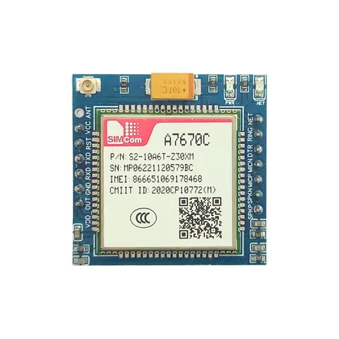
ADIY GSM SIMA7670C 4G BREAKOUT BOARD (Ver 1.1)
A7670C 4G Development Board A7670C 4G Development Board is a high-performance Cat-1 module that supports LTE-TDD/LTE-FDD wireless communication modes. With a maximum downlink rate of 10Mbps and an uplink rate of 5Mbps,…
₹1,200
Datasheet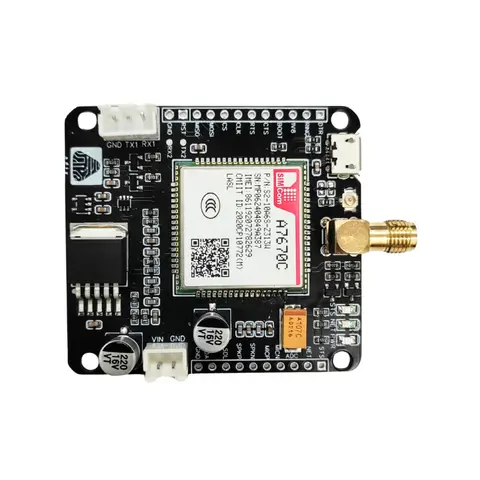
GSM Modules
SIMA7670C 4G/LTE GSM Board (LM39302) V1.1
The ADIY SIM A7670xx 4G LTE Board is a Cat-1 Module which supports wireless communication modes of LTE-TDD/LTE-FDD. It supports maximum 10Mbps downlink rate and 5Mbps uplink rate. This board features a serial interface…
₹1,447
Datasheet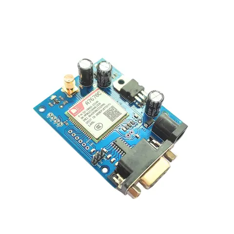
GSM Modules
ADIY GSM SIMA7670C 4G Module with RS232
GSM Module/4G LTE modem with SIM card socket, SMA antenna connector, DC power jack, and an RS232 interface supports wireless communication modes of LTE-TDD/LTE-FDD/GSM/GPRS/EDGE. Suitable for LTE and GSM networks. This…
₹1,385
Datasheet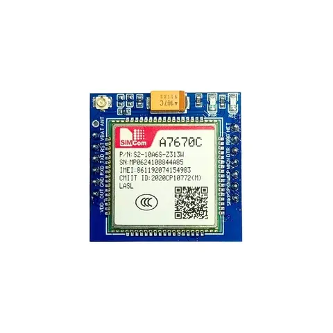
GSM Modules
ADIY GSM SIMA7670C 4G Breakout Board with logic level V1.2
The SIM A7670C 4G LTE breakout Board is a Cat 1 module that supports wireless communication modes of LTE-TDD/LTE-FDD/GSM/GPRS/EDGE. It supports a maximum 10Mbps downlink rate and a 5Mbps uplink rate It supports a…
₹1,425
Share