Interfacing & Displaysbeginnerdesign notes
Relay Modules Explained: Active-Low, Opto-Isolation and JD-VCC
Why relay modules switch on at LOW, what the optocoupler isolates, when to remove the JD-VCC jumper, AC vs DC contact ratings and fail-safe design.
By ADIY16 min read
Technical review pending. Figures marked “verify” or “check your part” have not been confirmed against your exact hardware revision. Check the manufacturer datasheet before relying on them in a design.
Three things about relay modules confuse almost everyone the first time: they turn on when you write LOW, the optocoupler does not isolate anything unless you remove a jumper, and the DC contact rating is far lower than the AC one. Each of those has a good engineering reason, and knowing them is the difference between a board that works and one that fails in the field.
1. What is actually on the board#
A relay module is a small collection of parts around an electromechanical relay, and understanding the chain explains every behaviour that follows.
| Stage | What it does |
|---|---|
| 1. Control input (IN1, IN2…) | Your microcontroller pin connects here. Draws only a few milliamps. |
| 2. Optocoupler (on isolated boards) | An LED and phototransistor in one package. Passes the signal as light, with no electrical connection between the two sides. |
| 3. Driver transistor | Switches the current the coil needs, which the control pin could not supply. |
| 4. Relay coil | An electromagnet. Energised, it pulls the contacts across. |
| 5. Flyback diode | Across the coil. Absorbs the reverse voltage spike when the coil de-energises. |
| 6. Contacts (COM, NO, NC) | The actual switch. Electrically separate from everything above. |
2. Why LOW turns it on#
The single most common first experience with a relay module is that everything is backwards. You upload a sketch, and the relays are all on until you tell them to be off.
Most of these boards are active-low: the relay energises when the control input is pulled to ground and de-energises when it is held high. This is not an oversight, and there are two good reasons for it.
Reason one: sinking beats sourcing#
Many microcontroller output stages can sink more current than they can source, and driving an optocoupler LED or a transistor base by pulling the line low is the more robust arrangement. It also means the drive current comes from the module supply rather than being pushed out of your microcontroller pin.
Reason two: the reset state#
This is the important one for anyone building something real. At power-up and during reset, microcontroller pins are inputs. They float, or sit weakly pulled up. They are not driving anything.
// Active-low relay control. Note the pattern:
// LOW = energised = load ON.
#define RELAY_1  7
// Named constants. Never write digitalWrite(RELAY_1, LOW)
// scattered through your code and expect to read it later.
#define RELAY_ON   LOW
#define RELAY_OFF  HIGH
void setup() {
  // CRITICAL ORDER: set the pin to the off state BEFORE
  // making it an output. Reverse these two lines and the
  // relay clicks on for a few microseconds at every boot.
  digitalWrite(RELAY_1, RELAY_OFF);
  pinMode(RELAY_1, OUTPUT);
}
void loop() {
  digitalWrite(RELAY_1, RELAY_ON);    // load on
  delay(2000);
  digitalWrite(RELAY_1, RELAY_OFF);   // load off
  delay(2000);
}
Active-low control with the pin initialised before it becomes an output.
3. What the optocoupler actually isolates#
ADIY stocks relay boards both with and without optocouplers, and the difference is worth understanding rather than defaulting to "isolated is better".
An optocoupler contains an LED and a photodetector facing each other in an opaque package. The signal crosses as light. There is no electrical connection between input and output. That buys you two things:
- Protection from coil switching noise. Relay coils generate voltage spikes when they de-energise. The flyback diode handles most of it, but noise still couples into the local supply and ground. An optocoupler stops that path back to your microcontroller.
- Ground loop breaking. If the relay side and the control side would otherwise have different ground references, the optocoupler prevents current flowing between them.
4. The JD-VCC jumper, and why it usually defeats the point#
Here is the part almost nobody explains. An opto-isolated board has two supply pins:
- VCC — powers the optocoupler input side, the side your microcontroller talks to
- JD-VCC — powers the relay coils, the side that switches
Boards ship with a jumper linking them, so a single 5 V supply powers everything and it works out of the box.
How to actually get isolation#
- Remove the JD-VCC jumper.
- Feed VCC and GND from your microcontroller supply, to the optocoupler input side.
- Feed JD-VCC and the relay-side ground from a completely separate supply. A separate adaptor, not a second output of the same one.
- Do not bond the two grounds anywhere. Connecting them defeats the whole exercise.
| Configuration | Isolation | Supplies | Use when |
|---|---|---|---|
| Jumper fitted | None in practice | One 5 V supply | Prototyping, low-voltage loads, learning |
| Jumper removed, two supplies | Genuine | Two independent supplies | Electrically noisy environments, motors, anything you care about |
| Jumper removed, one supply | None, and the relays will not switch | Misconfiguration | Never. This is the most common wiring mistake with these boards. |
5. Coil current, and why the eight-channel board misbehaves#
The control pin draws a few milliamps. The coil draws considerably more, and it is per relay.
Symptoms of an inadequate supply on a relay board:
- Relays chatter or buzz rather than latching cleanly
- The microcontroller resets when a relay switches
- Individual relays work, several together do not
- Behaviour changes when you switch from USB power to an adaptor
All of these say power, not code. Give the coils their own supply through JD-VCC before you start suspecting your firmware.
6. Contact ratings, and the AC versus DC trap#
Relay contacts carry a rating printed on the can, typically something like 10 A 250 V AC and 10 A 30 V DC. People read the first number and assume the relay handles 10 A of anything.
Inductive loads derate further#
The printed rating generally assumes a resistive load. Motors, solenoids, contactors and transformers store energy in a magnetic field and dump it across the contacts at switch-off, producing a much more severe arc. For inductive loads, derate substantially and consider suppression across the load, such as an RC snubber for AC or a diode for DC.
| Load | Character | Notes |
|---|---|---|
| Incandescent lamp | Resistive, high inrush | Cold filament draws several times running current for a moment. |
| Heater element | Resistive | The friendliest case. Rating applies most directly. |
| Motor | Inductive, high inrush | Derate hard. Starting current far exceeds running current. |
| Solenoid or valve | Inductive | Needs suppression across the load. |
| LED driver, SMPS | Capacitive input | Very high momentary inrush charging input capacitors. |
| Contactor coil | Inductive | Common in industrial use. Use the relay to drive the contactor, and the contactor to switch the real load. |
7. NO, NC and choosing your fail-safe state#
Each relay gives you three contact terminals:
- COM — common, the pole of the switch
- NO — normally open. Disconnected from COM when the coil is de-energised.
- NC — normally closed. Connected to COM when the coil is de-energised.
"Normally" means with no power applied to the coil. This is a design decision, not a wiring detail.
8. Mains safety#
If you are switching 230 V with any relay board:
- Never work on a live circuit. Isolate at the breaker, and verify with a tester that it is actually dead before touching anything.
- Enclose everything. Bare mains terminals on a board on a desk is how people get hurt. Use an enclosure that prevents contact with live parts.
- Maintain creepage and clearance. Keep mains wiring physically separated from low-voltage wiring. Do not run them through the same terminal block or bundle them together.
- Use appropriately rated wire for the current, with proper insulation and secure terminations. Screw terminals should be tight; a loose mains connection generates heat.
- Provide upstream protection. A relay is a switch, not a protective device. The circuit still needs a correctly rated breaker or fuse.
- Earth metal enclosures properly.
- Do not leave prototypes running unattended. A breadboarded mains project left switching overnight is a fire risk.
- Engage a licensed electrician for anything that becomes part of a building's fixed wiring. In India this is both a safety matter and a regulatory one.
9. Choosing a board#
| Requirement | Choose |
|---|---|
| Learning, one low-voltage load | 1 channel without optocoupler. Cheapest, perfectly adequate. |
| Anything with a motor or in a noisy environment | Opto-isolated, jumper removed, separate coil supply. |
| Controller runs on 12 V, no 5 V available | 12 V coil board. Match the coil voltage to the supply you have. |
| Home automation, several loads | 4 or 8 channel. Do the coil current sum first. |
| Industrial panel | Relay board driving properly rated contactors. |
| Isolation needed but not switching | A dedicated optocoupler module, no relay involved. |
| Silent operation, very frequent switching | Not a relay. Contacts wear out and click. Use a solid state device. |
FAQ#
Why does my relay module turn on when I write LOW?
Most relay modules are active-low by design. The control input drives a transistor or optocoupler that energises the coil when the input is pulled low. This is deliberate: microcontroller pins typically sink better than they source, and pins float or sit pulled-up at reset, which with active-low logic leaves the relay safely off during boot.
What is the JD-VCC jumper on a relay module?
On isolated boards, JD-VCC supplies the relay coils while VCC supplies the optocoupler input side. The jumper links them so one supply powers both, which is convenient but defeats the isolation, since the two sides then share supply and ground. Remove the jumper and feed JD-VCC separately for genuine isolation.
Can I drive a relay module directly from an Arduino pin?
The control input yes, the coil no. The control pin drives a transistor or optocoupler drawing a few milliamps. The coil draws considerably more and must come from the module supply. An eight channel board with all relays energised can exceed what a development board regulator will deliver.
Why is the DC contact rating lower than the AC rating?
AC crosses zero twice per cycle, which extinguishes the arc that forms as contacts separate. DC does not cross zero, so the arc sustains and erodes the contacts far more aggressively. A relay marked 10 A at 250 V AC may be rated only 10 A at 30 V DC. Take the DC rating literally.
Do I need a flyback diode with a relay module?
On a ready-made module it is already fitted across the coil. You need one if driving a bare relay from your own transistor circuit. Separately, an inductive load such as a motor or solenoid may need its own suppression, since that energy appears across the contacts rather than the coil.
Sources#
Sources and further reading#
- Relay manufacturer datasheets for coil current, contact ratings and electrical life figures. These vary by relay part, so consult the datasheet for the relay fitted to your board.
- Sharp PC817 optocoupler datasheet for isolation characteristics.
- General relay application literature on arc suppression and AC versus DC switching behaviour.
Products & resources
- A85128 ADIY 1 CHANNEL RELAY BOARD WITHOUT OPTO 5V Datasheet(1)
- 1 Channel Relay Board-5V Datasheet
- 1 CHANNEL RELAY BOARD WITH OPTO 12V Datasheet
- 2 Channel Relay Board-5V Datasheet
- 2 Channel Relay Board-12V Datasheet
- 3 channel with Opto 5V Datasheet
Relay Boards
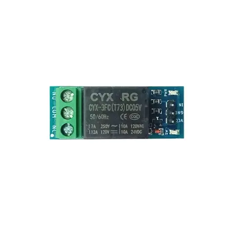
ADIY 1 CHANNEL 5V RELAY BOARD WITHOUT OPTO
Relay Module 5v 1 Channel SPDT (Single-Pole Double-Throw) high-level trigger AC power relay board is designed for easy integration with microcontrollers, allowing direct control of up to 10A at 250 VAC. The relay’s…
₹47
Datasheet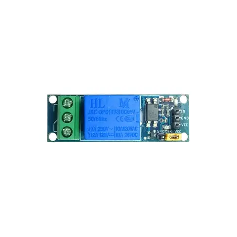
Relay Boards
ADIY 1 CHANNEL 5V RELAY BOARD WITH OPTO
5 V Relay Module with 1 Channel is designed for switching only a single high-powered device from your Arduino. This 1 channel 5V 10A relay control board module with optocoupler modules is compliant with international…
₹61
Datasheet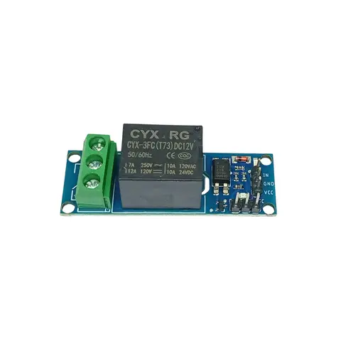
Relay Boards
ADIY 1 CHANNEL 12V RELAY BOARD WITH OPTO
12V 1-Channel Relay Module with Optocoupler by ADIY is a Bidirectional isolation type 1-Channel relay control module, according to user needs, you can choose a high or low level to control the relay pull. The module…
₹61
Datasheet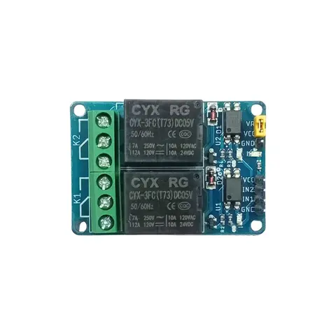
Relay Boards
ADIY 2 CHANNEL 5V RELAY BOARD
Relay Module 5V 2 Channel contains two relays that are electrically isolated from the controlling input. The relays can be used to switch higher voltage and current loads than a microcontroller can traditionally…
₹87
Datasheet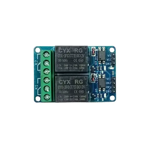
Relay Boards
ADIY 2 CHANNEL 12V RELAY BOARD
2 Channel 12V Relay Module with Optocoupler by ADIY is an interface board and can be controlled directly by a wide range of microcontrollers such as Arduino, AVR, PIC, ARM, and so on. With digital outputs to control…
₹87
Datasheet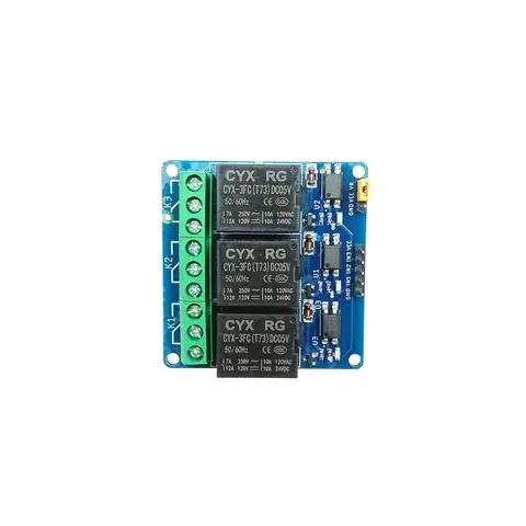
Relay Boards
ADIY 3 CHANNEL 5V RELAY BOARD
Relay Module 5v 3 Channel & Optocoupler By ADIY allows you to control larger loads and devices like AC or DC motors, fans, light bulbs, etc. Specifications: Relay Board 5V 3 Channel • Reverse polarity protection. •…
₹160
Datasheet
Share