Sensorsintermediatecomponent deep dive
MQ Gas Sensor Calibration: Getting Real ppm from MQ2 and MQ135
Why most MQ135 and MQ2 code gives meaningless ppm, how to find Ro in clean air, derive the curve constants, and what these sensors cannot measure.
By ADIY16 min read
Technical review pending. Figures marked “verify” or “check your part” have not been confirmed against your exact hardware revision. Check the manufacturer datasheet before relying on them in a design.
Nearly every MQ135 tutorial online produces a number labelled "ppm" that is not a measurement of anything. This article explains why, shows the calibration procedure that makes the reading meaningful, and is honest about what these sensors fundamentally cannot do.
1. How an MQ sensor actually works#
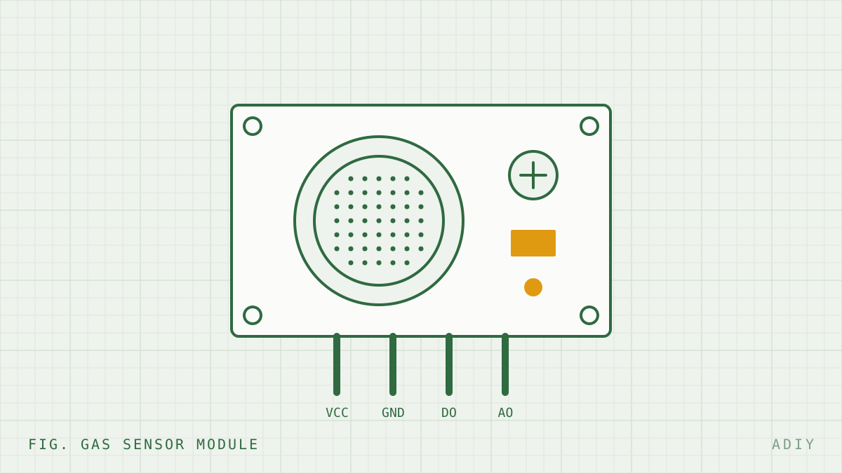
Inside the steel mesh cap is a small ceramic tube coated with tin dioxide, and a heater coil running through it. The heater holds the tin dioxide at a few hundred degrees Celsius. At that temperature, atmospheric oxygen adsorbs onto the surface of the tin dioxide and traps free electrons, which raises the resistance of the material.
When a reducing gas such as ammonia, alcohol vapour, LPG or carbon monoxide reaches the hot surface, it reacts with that adsorbed oxygen. The reaction releases the trapped electrons back into the material, and the resistance falls. More gas means more reaction means lower resistance.
Three consequences follow directly from this mechanism, and they explain almost everything about how these sensors behave:
- The output is a resistance, not a voltage or a concentration. Everything downstream is your inference.
- The sensor is not selective. Any reducing gas that reacts with adsorbed oxygen will lower the resistance. The sensor has no way to tell you which gas it was.
- The absolute resistance is not meaningful, only the ratio is. The manufacturing tolerance on the tin dioxide layer is wide, so two sensors from the same batch can have very different absolute resistances in identical air. What is repeatable is the ratio of the current resistance to a reference resistance measured in known conditions.
That third point is the entire basis of calibration, and it is what tutorial code usually ignores.
2. Why typical tutorial code is wrong#
The pattern you see everywhere looks roughly like this:
// This is the pattern to avoid.
int raw = analogRead(A0);
float ppm = raw * 1.2;          // where does 1.2 come from?
Serial.print("CO2: "); Serial.println(ppm);
There are four separate errors compressed into those three lines:
- A magic scaling constant. There is no linear relationship between ADC counts and concentration. The relationship is a power law, and it is different for every target gas.
- No Ro. Without a per-sensor reference resistance, the reading cannot be compared to the datasheet curve or to another sensor.
- An assumed load resistor. The calculation implicitly assumes some RL value which may not be what is fitted on the board.
- A gas label the sensor cannot justify. Calling MQ135 output "CO2" is the most common one. See section 8.
The result is a number that moves in the right direction when you breathe on the sensor, which is enough to look convincing in a demo video and not enough to be a measurement.
3. Step 1: verify your load resistor#
The sensing element sits in a voltage divider with a load resistor RL, and the analog output is the voltage across RL. You cannot compute the sensor resistance without knowing RL accurately.
| Parameter | Value | Status |
|---|---|---|
| Load resistance RL, recommended | approx. 20 kΩ | Datasheet (source stated) |
| Load resistance RL, acceptable range | 10 kΩ to 47 kΩ | Datasheet (source stated) |
| Ro definition | Sensor resistance at 100 ppm NH3 in clean air | Datasheet (source stated) |
| Sensitivity curve conditions | 20 °C, 65 % RH, RL = 20 kΩ | Datasheet (source stated) |
| RL actually fitted on your module | Unknown until measured | Must verify (verify before relying on this) |
If the fitted RL is far outside the datasheet range, you have two options. Either replace it with a value in range, which is the cleaner fix, or calibrate empirically against a reference instrument, which is more work but avoids rework on an assembled board.
4. Step 2: compute Rs correctly#
With a known RL, the sensing resistance follows from the divider. For a sensor supplied at VC with output voltage Vout across RL:
RS = RL × ( VC − Vout ) / Vout
And Vout comes from the ADC:
Vout = ADCraw × Vref / (2n − 1)
On a 5 V Arduino Uno with a 10-bit ADC that denominator is 1023. On a 3.3 V board with a 12-bit ADC it is 4095, and Vref changes too. Getting this wrong is a common source of a constant offset that people then "fix" with another magic constant.
5. Step 3: determine Ro in clean air#
Ro is the anchor for everything else. The MQ-135 datasheet defines it as the sensor resistance at 100 ppm ammonia in clean air. Most of us do not have a calibrated 100 ppm ammonia atmosphere available, so the practical approach is to measure Rs in clean air and apply the clean air factor from the datasheet curve, which is the ratio Rs/Ro in clean air.
The procedure#
- Burn in the sensor. A new sensor needs an extended initial preheat before its readings stabilise. Guidance commonly cited is 24 to 48 hours powered continuously. Skipping this is the second most common calibration error after ignoring RL, because a fresh sensor drifts steadily downward over the first day and any Ro captured during that window is wrong.
- Get genuinely clean air. Outdoors, away from traffic, cooking, solvents, cleaning products and people. An indoor room is not clean air for this purpose. Early morning outdoor air is a reasonable practical reference.
- Allow thermal equilibrium. Even after burn-in, allow several minutes after each power-up for the heater to stabilise before recording.
- Average heavily. Take a few hundred samples over a minute or two and average. Single readings are noisy.
- Divide by the clean air factor from your sensor's datasheet curve to obtain Ro.
Ro = RS(clean air) / cleanAirFactor
Store Ro, do not recalculate it every boot#
Ro should be determined once per sensor, in controlled conditions, and written to EEPROM or flash. Code that recalibrates Ro on every power-up is silently assuming the device always boots in clean air. If your gas alarm boots during a gas leak, self-calibrating firmware will treat the leak as its clean air baseline and then report zero. That is a safety-relevant failure mode and it is present in a surprising amount of published code.
6. Step 4: derive the curve constants#
The datasheet sensitivity graph is plotted on log-log axes, and on log-log axes the gas response curves are close to straight lines. A straight line on log-log axes is a power law:
ppm = a × ( RS / Ro )b
To find a and b for your target gas, read two well-separated points off that gas's line on the datasheet graph. Each point gives you a (ratio, ppm) pair. Then:
b = log(ppm2 / ppm1) / log(ratio2 / ratio1)
a = ppm1 / ratio1b
Note that b is negative for these sensors, because resistance falls as concentration rises.
7. Complete Arduino calibration sketch#
/*
 * ADIY Labs — MQ series calibration and ppm calculation
 *
 * Two-phase sketch:
 *   Phase 1 (CALIBRATION_MODE 1): run outdoors in clean air, read Ro
 *                                 from the serial monitor, note it down.
 *   Phase 2 (CALIBRATION_MODE 0): paste Ro below and deploy.
 *
 * IMPORTANT: RL_KOHM, CLEAN_AIR_FACTOR, CURVE_A and CURVE_B below are
 * placeholders. You must fill them from YOUR module's measured load
 * resistor and YOUR sensor's datasheet curve. See sections 3, 5 and 6.
 *
 * NOT bench-verified in this revision. Verify before relying on it.
 */
#include
#define CALIBRATION_MODE   1        // 1 = find Ro, 0 = measure ppm
#define MQ_PIN             A0
#define ADC_MAX            1023.0   // 10-bit AVR. Use 4095.0 for 12-bit.
#define VC                 5.0      // MEASURE your actual rail, do not assume.
#define VREF               5.0      // ADC reference.
// --- FILL THESE IN FOR YOUR HARDWARE ---------------------------------
#define RL_KOHM            20.0     // MEASURED load resistor, in kilohms.
#define CLEAN_AIR_FACTOR   3.6      // From YOUR datasheet curve. Placeholder.
#define CURVE_A            110.0    // From YOUR two-point fit. Placeholder.
#define CURVE_B            -2.86    // Negative. From YOUR fit. Placeholder.
#define RO_KOHM            10.0     // Result of phase 1. Placeholder.
// ---------------------------------------------------------------------
#define SAMPLES            200
#define SAMPLE_GAP_MS      50
#define WARMUP_MS          180000   // 3 min thermal settle after power-up.
// Average many ADC samples to beat down noise.
float readAveragedAdc() {
  float sum = 0;
  for (int i = 0; i < SAMPLES; i++) {
    sum += analogRead(MQ_PIN);
    delay(SAMPLE_GAP_MS);
  }
  return sum / SAMPLES;
}
// Convert averaged ADC counts to sensing resistance, in kilohms.
float adcToRs(float adc) {
  float vout = adc * VREF / ADC_MAX;
  // Guard against divide-by-zero if the sensor is disconnected.
  if (vout < 0.01) return -1.0;
  return RL_KOHM * (VC - vout) / vout;
}
// Power law from the datasheet log-log curve.
float rsRatioToPpm(float ratio) {
  return CURVE_A * pow(ratio, CURVE_B);
}
void setup() {
  Serial.begin(115200);
  Serial.println("\n=== ADIY MQ sensor ===");
  Serial.println("Warming up. Readings before thermal settle are not valid.");
  delay(WARMUP_MS);
#if CALIBRATION_MODE
  Serial.println("CALIBRATION MODE");
  Serial.println("Sensor must be in clean outdoor air, post burn-in.");
  float adc = readAveragedAdc();
  float rs  = adcToRs(adc);
  if (rs < 0) {
    Serial.println("ERROR: output near zero. Check wiring and supply.");
    return;
  }
  float ro = rs / CLEAN_AIR_FACTOR;
  Serial.print("Averaged ADC : "); Serial.println(adc, 1);
  Serial.print("Rs (kOhm)    : "); Serial.println(rs, 2);
  Serial.print("Ro (kOhm)    : "); Serial.println(ro, 2);
  Serial.println("\nPut this Ro into RO_KOHM, set CALIBRATION_MODE 0, reflash.");
#else
  Serial.println("MEASUREMENT MODE");
  Serial.print("Using Ro = "); Serial.print(RO_KOHM); Serial.println(" kOhm");
#endif
}
void loop() {
#if !CALIBRATION_MODE
  float adc   = readAveragedAdc();
  float rs    = adcToRs(adc);
  if (rs < 0) { Serial.println("Sensor fault"); delay(2000); return; }
  float ratio = rs / RO_KOHM;
  float ppm   = rsRatioToPpm(ratio);
  // Report the ratio too. It is the honest primary measurement;
  // ppm is an inference layered on top of it.
  Serial.print("Rs/Ro = "); Serial.print(ratio, 3);
  Serial.print("   est. ppm = "); Serial.println(ppm, 1);
  delay(2000);
#endif
}
Two-phase calibration sketch. The placeholder constants must be replaced with values from your own hardware and datasheet.
8. What MQ sensors cannot do#
This section will lose us some sales and it is worth writing anyway.
The MQ135 is not a CO2 sensor#
You will find a great many projects that read an MQ135 and print a CO2 figure in ppm. The mechanism described in section 1 does not support this. The MQ135 responds broadly to reducing gases, ammonia, alcohols, benzene, smoke among them. Carbon dioxide is not a reducing gas in the sense that drives this reaction, and the sensor has no means of distinguishing CO2 from anything else even if it did respond.
What those projects are really doing is assuming an atmosphere whose composition tracks CO2, then reporting the sensor's general response as though it were a CO2 measurement. In a room where the only thing changing is human respiration, the number will move in roughly the right direction, which is why the approach survives. Introduce a cleaning product, a gas hob, or a person wearing perfume and the reading becomes nonsense.
Selectivity is limited across the whole family#
The same caution applies to the family generally, in proportion. An MQ2 responds to LPG, propane, hydrogen, methane, alcohol and smoke. It cannot tell you which one it is seeing. That is entirely fine for a "something combustible is present" alarm, which is what these sensors are genuinely good at. It is not fine for a claim about a specific gas concentration.
These are not safety-certified devices#
9. Temperature and humidity#
The datasheet sensitivity curve is specified at a single condition, for the MQ-135 that is 20 °C and 65 % relative humidity. Real deployments are not at that condition, and the sensing mechanism is temperature and humidity dependent because both affect surface adsorption.
Datasheets for these sensors typically include a second graph showing the Rs/Ro ratio against temperature and humidity, usually as a family of curves at different humidity levels. If you are deploying anywhere with meaningful environmental swing, and in most of India that is everywhere, you should:
- Add a temperature and humidity sensor alongside the MQ sensor
- Read the correction factor off the datasheet environmental curve
- Apply it to your ratio before computing ppm
Even with correction, be realistic about the accuracy you are claiming. A corrected, individually calibrated MQ sensor gives you a usefully repeatable trend. It does not give you an instrument-grade concentration, and published research on environmental influence on MQ-135 output ratios supports treating these as indicative rather than absolute.
FAQ#
Can the MQ135 measure CO2 concentration?
Not reliably. The MQ135 is a broadband metal oxide sensor that responds to a range of reducing gases including ammonia, alcohols, benzene and smoke. It has no mechanism to distinguish CO2 from those. Any CO2 ppm figure derived from an MQ135 is an inference from an assumed atmosphere, not a measurement. For genuine CO2 measurement use an NDIR sensor.
What is Ro in MQ sensor calibration?
Ro is the sensing element resistance at a defined reference condition. For the MQ135 the datasheet defines it as the sensor resistance at 100 ppm ammonia in clean air. Because manufacturing tolerance on the sensing element is wide, Ro varies substantially between individual sensors, which is why every sensor must be calibrated individually rather than using a value from a library.
How long does an MQ sensor need to burn in?
Manufacturer guidance and field practice both point to an extended preheat before readings stabilise, commonly cited as 24 to 48 hours for a new sensor. On every subsequent power-up allow several minutes for the heater to reach thermal equilibrium. Readings taken in the first minutes after power-up drift significantly and should be discarded.
Why does my MQ135 give a different reading than another identical module?
Two reasons. First, sensing element tolerance means Ro differs between units, so an uncalibrated reading is not comparable. Second, the load resistor fitted on the module varies between manufacturers and is often not the value the datasheet recommends. Measure the load resistor on your specific board and calibrate each sensor individually.
Should I use the digital output pin on an MQ module?
Only as a crude threshold alarm. The digital pin is the output of an onboard comparator with a potentiometer-set trip point. It carries no concentration information. For any measurement, use the analog output and compute the ratio of sensor resistance to Ro.
Sources#
Sources and further reading#
- Hanwei Electronics, Technical Data MQ-135 Gas Sensor. Source for RL recommended value and range, Ro definition, and sensitivity curve reference conditions.
- Hanwei Electronics datasheets for MQ-2, MQ-3 and MQ-4, for the corresponding per-sensor curve constants and clean air factors.
- Published research on the influence of temperature and humidity on MQ-135 output resistance ratio, supporting the environmental correction discussion in section 9.
- Community reports of load resistor values fitted on commercial MQ breakout modules differing from datasheet recommendations. Treated here as a prompt to measure your own board rather than as a claim about any specific manufacturer.
Products & resources
- MQ135 GAS SENSOR MODULE Datasheet
- A85653 Methane CNG Gas Sensor-MQ4 Datasheet
- MQ3 GAS SENSOR MODULE Datasheet
- ADIY LM393 Comparator Datasheet
- MQ2 Gas Sensor Module Datasheet
Gas Sensors
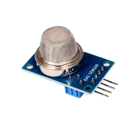
MQ135 Air Quality Sensor Module – ADIY
MQ-135 Gas sensor can detect gases like Ammonia (NH3), sulfur (S), Benzene (C6H6), CO2, and other harmful gases and smoke. Similar to other MQ series gas sensor, this sensor also has a digital and analog output pin.…
₹119
Datasheet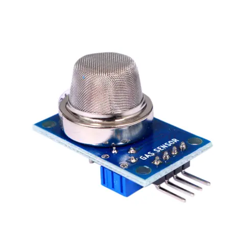
Gas Sensors
MQ4 Methane CNG Gas Sensor Module – ADIY
MQ4 methane gas sensor Module is designed to detect methane (CH4) and CNG gas leaks in homes and industries. It provides rapid response and high sensitivity, adjustable via a potentiometer. The sensor outputs an analog…
₹110
Datasheet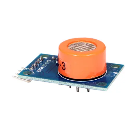
Gas Sensors
MQ3 Gas Sensor Module – ADIY
MQ3 Alcohol Sensor Module is made using Alcohol Gas Sensor MQ3. It is a low-cost semiconductor sensor that can detect the presence of alcohol gases at concentrations from 0.05 mg/L to 10 mg/L. The sensitive material…
₹125
Datasheet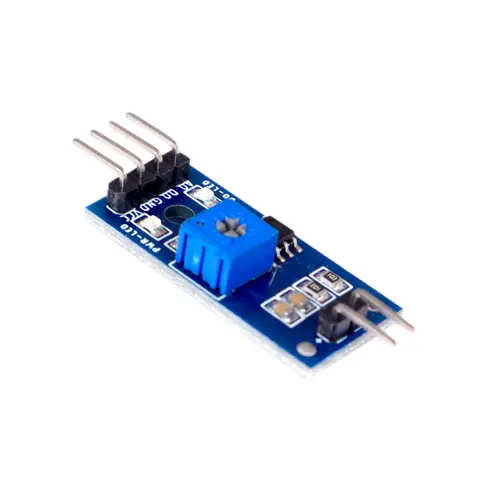
Converter Boards
LM393 Comparator Module – ADIY
The comparator LM393 module is used to digitize any resistive sensor. The module produces an output voltage according to the resistance of the connected sensor and is made available at the Analog Output (AO) pin. The…
₹33
Datasheet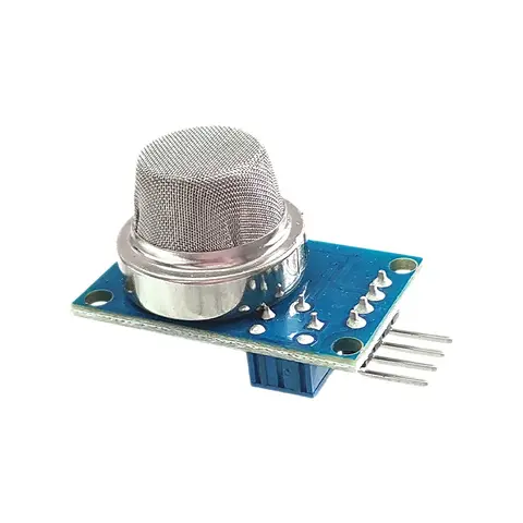
Gas Sensors
ADIY MQ2 Gas Sensor Module
ADIY MQ2 gas sensor is an electronic sensor used for sensing the concentration of gases in air such as LPG, Propane, Methane, Hydrogen, alcohol, smoke, and carbon monoxide. MQ2 gas sensor is also known as chemiresistor.…
₹109
Datasheet
Share