Engineering Skillsbeginnerfundamentals
How to Read an Electronics Datasheet: Essential Skill for Every Engineer
Learn to read an electronics datasheet: key sections, absolute maximum ratings and electrical characteristics, with LM7805, ATmega328P and L298N examples.
By ADIY13 min read
Technical review pending. Figures marked “verify” or “check your part” have not been confirmed against your exact hardware revision. Check the manufacturer datasheet before relying on them in a design.
1. Introduction — Why datasheets terrify beginners (and why they shouldn't)#
If you've ever embarked on an electronics project, building an IoT dashboard with a new sensor, or assembling an automation circuit, you’ve likely stumbled upon a document that looks more like a PhD thesis than a user manual. These are datasheets. To many beginners, diving into a 50-page PDF filled with dense jargon, mathematical formulas, and confusing timing diagrams can be incredibly intimidating.
It is a common scenario in India’s bustling engineering colleges and makerspaces: a student gets an ADIY UNO R3 or a random motor driver, searches online for how it works, clicks a datasheet link, and is instantly overwhelmed by a wall of text detailing "input capacitance," "thermal resistance," and "logic low thresholds." They immediately close the tab and try to find a YouTube tutorial instead.
However, ignoring the datasheet is a dangerous game. It often leads to burnt-out microcontrollers, malfunctioning sensors, and hours of debugging phantom issues that could have been avoided with a 3-minute glance at the right table. The truth is: you are not supposed to read a datasheet from cover to cover like a novel. You are supposed to use it like an encyclopedia. Once you understand the standard structure of these documents, extracting the exact information you need—whether it’s the maximum voltage, the I2C address, or the pinout—becomes second nature.
In this comprehensive electronics datasheet guide, the ADIY Engineering Team will demystify the datasheet. We will break down its anatomy, walk through real-world examples using common components available in India, and provide you with a glossary of essential terms. By the end of this tutorial, you will possess a core skill that separates amateur hobbyists from professional engineers.
2. What is a Datasheet?#
A datasheet is an official instructional and technical document provided by the manufacturer of an electronic component. Whether the component is a simple resistor, an LED, a complex motor driver, or a high-end microprocessor, its manufacturer publishes a datasheet to communicate exactly how the device behaves under various conditions.
Who writes them? They are written by the application engineers and chip designers at the semiconductor companies (like Texas Instruments, Microchip, STMicroelectronics, etc.). They are written for other engineers to facilitate the integration of the component into larger systems.
When you purchase products from ADIY, we ensure that relevant documentation, pinouts, and references are available to streamline your development process under the 'Make in India' initiative. But understanding the original silicon datasheet is still paramount.
3. Anatomy of a Datasheet — The 8 Key Sections#
While every manufacturer has their own formatting style, the semiconductor industry has largely standardized the flow of information. Let's explore the 8 critical sections you will find in almost every datasheet.
a. Features / Description#
The very first page is essentially the component's resume or sales pitch. It provides a high-level overview of what the chip is, what it does, and its primary selling points (e.g., "Low Power," "High Speed," "I2C Interface"). It usually lists common applications and use cases. If you are searching for a part for a project, this page tells you if you are in the right ballpark.
b. Pin Configuration / Pinout#
This is arguably the most referenced section for hobbyists. It shows a diagram of the physical chip with labels for every single pin. It is crucial for wiring your circuit correctly. It will distinguish between power pins (VCC, GND), input/output pins, and specialized communication pins (TX, RX, SDA, SCL).
c. Absolute Maximum Ratings#
If there is one section you must read, it is this one. The Absolute Maximum Ratings specify the extreme limits the device can tolerate before it is permanently damaged or destroyed.
WARNING: These are not the recommended operating conditions. If a datasheet says the absolute maximum voltage is 6.0V, operating it at 5.9V is a terrible idea. These values represent the physical breaking point of the silicon. Always design your circuit to operate well below these limits to ensure longevity and reliability.
d. Electrical Characteristics#
This section is a massive table (or series of tables) detailing how the component behaves under normal, recommended operating conditions. It is usually broken down into Min, Typ (Typical), and Max columns.
Here you will find critical parameters like:
- Supply Voltage (VCC/VDD): The voltage required to power the chip.
- Supply Current (ICC/IDD): How much current the chip consumes.
- Logic Levels (VIH, VIL, VOH, VOL): The voltage thresholds that determine what the chip considers a digital HIGH (1) or LOW (0). This is vital when interfacing 3.3V logic devices (like the ADIY FLY Pico RP2040) with 5V logic devices (like the ADIY UNO R3).
e. Functional Description#
This section explains the internal workings of the chip. It might include a block diagram showing the internal logic gates, shift registers, ALUs, or multiplexers. For complex microcontrollers, this section can span hundreds of pages, detailing every internal register, memory map, and peripheral (timers, ADCs, UARTs) configuration.
f. Application Circuit#
Manufacturers want you to succeed in using their product. Therefore, they often provide "Typical Application Circuits" or "Reference Designs." These are pre-designed schematic diagrams showing exactly how to wire the chip for a standard use case, complete with recommended values for external components like decoupling capacitors and pull-up resistors. Pro Tip: When in doubt, copy the reference design!
g. Timing Diagrams#
For digital ICs that rely on clocks (like shift registers, SPI/I2C devices, or memory chips), timing diagrams are essential visual representations of the required sequence of digital signals. They illustrate concepts like Setup Time (how long data must be stable before a clock edge) and Hold Time (how long data must remain stable after a clock edge).
h. Package Information#
Located at the very end, this section provides the exact physical dimensions of the chip in millimeters or inches. It includes the recommended PCB land pattern (footprint) required if you are designing your own custom Printed Circuit Board. It details different package variants (e.g., DIP, SOIC, QFN) since the same silicon die can be housed in various physical formats.
4. Worked Example 1: LM7805 Voltage Regulator Datasheet#
Let’s apply this to a classic component: the LM7805, a ubiquitous 5V linear voltage regulator used in countless student projects across India to convert a 9V or 12V battery down to a stable 5V for microcontrollers.
If we open a standard LM7805 datasheet, here is how we extract the critical info:
- Pinout: We check the diagram for the TO-220 package. Looking at the front (where the writing is), the pins from left to right are 1: Input, 2: Ground, 3: Output.
- Absolute Maximum Ratings: We look for the maximum input voltage. The datasheet will typically state
VI = 35V. Connecting a 40V source will destroy it. - Electrical Characteristics: We look for the required input voltage to maintain a stable 5V output. We find the Dropout Voltage parameter is typically 2V. This means the input voltage must be at least 2V higher than the output (5V + 2V = 7V). So, powering an LM7805 with a 6V battery will result in an unstable output!
- Thermal Data: Linear regulators get hot. We check the Thermal Resistance (θJA) to calculate if we need an external heatsink based on the power we are dissipating.
5. Worked Example 2: ATmega328P (The Heart of ADIY UNO R3)#
The ATmega328P is the microcontroller that powers the beloved ADIY UNO R3. Its datasheet is a massive document (often over 300 pages). You don't read this; you search it.
- Need to know the ADC resolution? Jump to the "Analog-to-Digital Converter" section. You'll find it features a 10-bit ADC, meaning it maps analog voltages between 0 and 5V into integer values from 0 to 1023.
- Need to handle maximum current? Go to "Absolute Maximum Ratings." You will see that the DC Current per I/O Pin is 40.0 mA. If you try to drive a high-power motor directly from an Arduino pin, it will draw more than 40mA and instantly fry that pin (or the whole chip). This is why you must use a motor driver.
- Setting up UART? The datasheet provides precise tables calculating the required register values for standard baud rates (9600, 115200) based on the 16MHz clock crystal used on the UNO.
6. Worked Example 3: L298N Motor Driver#
Since the ATmega328P cannot drive motors directly, you might use an L298N motor driver. The datasheet is crucial here.
- Current Rating: The features section boasts "Total DC Current up to 4A." But looking closely at the Electrical Characteristics, the continuous DC operation is rated at 2A per channel.
- Logic Control: The functional description provides a Truth Table. This table dictates exactly how to control the motor direction. For example, if Input 1 is HIGH and Input 2 is LOW, the motor turns clockwise. If both are HIGH, the motor fast motor stops (brakes).
- Voltage Drop: A critical detail often missed by beginners is the internal voltage drop. The Darlington transistors inside the L298N drop around 1.4V to 2V. If you supply 7V to the motor driver, your motors will only receive about 5V!
7. Common Datasheet Terms Glossary#
To help you navigate, the ADIY Engineering team has compiled this quick-reference glossary of the most common acronyms you will encounter in electronics datasheets:
| Abbreviation | Term | Meaning in Plain English |
|---|---|---|
| VCC / VDD | Positive Supply Voltage | The positive power connection required to run the chip (e.g., 5V or 3.3V). |
| GND / VSS | Ground | The negative terminal / 0V reference of the power supply. |
| VIH | Voltage Input High | The minimum voltage required for the chip to recognize an input signal as a digital '1'. |
| VIL | Voltage Input Low | The maximum voltage the chip will recognize as a digital '0'. |
| VOH | Voltage Output High | The minimum guaranteed voltage the chip will output when sending a digital '1'. |
| VOL | Voltage Output Low | The maximum guaranteed voltage the chip will output when sending a digital '0'. |
| I_CC / I_DD | Supply Current | How much current the chip consumes simply to operate. |
| I_OH / I_OL | Output Current High/Low | The maximum current the pin can source (supply) or sink (absorb). |
| t_pd | Propagation Delay | The time it takes for a signal to travel from the input of the chip to its output. |
| P_D | Power Dissipation | The maximum amount of power (heat) the package can safely shed. |
8. Tips for Reading Datasheets Faster#
Mastering datasheets takes practice. Here are 5 pro tips from our engineering team to accelerate your workflow:
- Ctrl+F is your best friend: Never scroll manually. Use the search function to look up specific terms like "I2C address," "baud rate," or "maximum current."
- Rely on the Index: For microcontroller datasheets (100+ pages), the hyperlinked table of contents or index is essential.
- Look at the diagrams first: A well-drawn block diagram or application circuit often explains 80% of what you need to know about integrating the component.
- Distinguish Typical from Guaranteed: In electrical tables, the "Typ" (Typical) column is what you will usually see, but the "Min/Max" columns are the guaranteed limits you must design your worst-case scenarios around.
- Check the Revision History: Chips evolve. Silicon bugs are fixed. Always ensure you are reading the latest revision of the datasheet to avoid designing around deprecated specifications.
9. Red Flags in Datasheets#
Not all datasheets are created equal, especially when sourcing ultra-cheap components from unknown overseas manufacturers instead of reliable Indian brands like ADIY. Watch out for these red flags:
- Missing Min/Max Values: If a datasheet only provides "Typical" values and omits the minimums and maximums, the manufacturer is not guaranteeing the performance spread of their silicon. This is a sign of poor quality control.
- Conflicting Information: Sometimes the features page will advertise a high spec (e.g., "5A peak current") but the electrical characteristics table restricts it severely (e.g., "5A peak for 1ms, 1A continuous"). Always trust the detailed tables over the marketing bullet points on page one.
- "Preliminary" Watermarks: If the datasheet says "Preliminary" or "Advance Information," the silicon is still in testing. Specifications are subject to change without notice.
10. Frequently Asked Questions (FAQ)#
Products & resources
Arduino Compatible
Uno R3 – Compatible CP2102
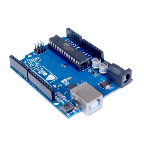
The ADIY Uno R3 CP2102 ATmega328P Development Board is a cost-effective alternative to the popular Arduino Uno R3. It is designed for beginners and professionals alike, offering robust performance and reliability. Key…
₹552
Datasheet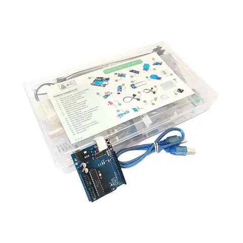
Arduino Compatible
UNO R3 Beginner kit – ADIY
ADIY Uno R3 Beginners Kit is a Stepping Stone for beginners who want to learn about electronic sensors and are excited to make projects. Beginners can learn the basics of UNO programming. Great for Starting with Arduino…
₹1,469
Datasheet
Share